Parts:
P1,P2__________220K  Linear Potentiometers (or 250K)
P3______________10K  Linear Potentiometer
P4_______________1M  Log. Potentiometer

R1_______________1M  1/4W Resistor
R2,R3___________68K  1/4W Resistors
R4,R5,R6,R7,R8_100K  1/4W Resistors

C1,C7___________47µF  25V Electrolytic Capacitors
C2_____________220pF  63V Ceramic or Polystyrene Capacitor (or 250pF)
C3_____________100nF  63V Polyester Capacitor
C4______________47nF  63V Polyester Capacitor
C5_____________100µF  35-50V Electrolytic Capacitor
C6_____________120pF  63V Ceramic or Polystyrene Capacitor
C8______________47nF  63V Polyester Capacitor

Q1,Q2,Q3,Q4__2N3819  General-purpose N-Channel FETs

J1,J2_________6.3mm  Mono Jack sockets

SW1____________SPST Toggle or Slide Switch
Circuit modifications:
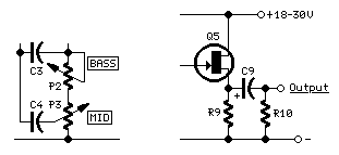
Marshall Tone Controls Parts:
P2_______________1M  Linear Potentiometer
P3______________22K  Linear Potentiometer (or 25K)

R6______________33K  1/4W Resistor

C2_____________470pF  63V Ceramic or Polystyrene Capacitor (or 500pF)
C3,C4___________22nF  63V Polyester Capacitors
Output buffer Parts:
R9______________10K  1/4W Resistor
R10____________100K  1/4W Resistor

C9_______________4µ7  63V Electrolytic Capacitor

Q5___________2N3819  General-purpose N-Channel FET
Notes:
- A very interesting discussion about Fender and Marshall Tone Controls, showing differences, frequency response graphics and much more can be found at Guitar Amplifier Basics
- Please note that all impedances involved in this circuit are very high (valve like, typically 1M) compared to common transistor circuitry: therefore, to avoid noise and hum pick-up, all connections must be kept very short and if input and output jacks and the pots are not directly mounted on a printed circuit board, all wiring to these parts must be done carefully by means of screened cable.
- In their more recent amplifier types, like '59 Bassman and Blues De Ville/Deluxe, Fender designers have slightly modified the Tone Controls parts values, thus obtaining a sort of compromise between their older models and Marshall Tone Controls. The changes were as follows: C2 and P1 (Treble Control) were left unchanged; C3 was still a 100nF capacitor but P2 value (Bass Control) was raised to 1M (log.) like the Marshall preamp. C4 and P3 (Mid Control) were changed to 22nF and 22K (or 25K) respectively: i.e. the same values and connections of the Marshall preamp modification as shown in the above schematics (left side).
Technical data
- Input Sensitivity @ 1KHz:
- 6mV RMS (Tone Controls set to center position, Volume control set to max.)
- Maximum undistorted output with 6mV RMS input:
- 3V RMS @ 18V supply
- 4V RMS @ 24V supply
- 5V RMS @ 30V supply
Total harmonic distortion @ 1KHz: <0.3% at 1V RMS output
Total current drawing at all supply voltages (18 to 30V): 8.5mA
Source : http://www.redcircuits.com/Page120.htm


0 komentar:
Posting Komentar